An automatic transfer switch is an electromechanical device that redirects the source of electrical power from a primary power supply to a backup power supply in the event of a power outage. These switches are often used in conjunction with a generator, connecting the generator’s electrical output to the electrical input of the system to be powered (i.e. hospitals, commercial buildings, homes, etc.). Figures 1 and 2 show a simple diagram that outlines the role of an ATS in this type of electrical system.

Figure 1: Simplified schematic of an Automatic Transfer Switch when the electric utility is running properly.
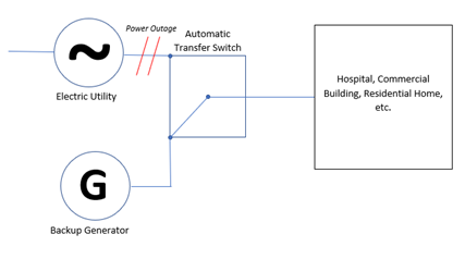
Figure 2: In the event of a power outage, the ATS will connect the backup generator to the electrical system, automatically preventing a sustained blackout.
Automatic transfer switches are commonly used in safety-critical applications and thus, must operate with a high degree of reliability. Hospitals, for instance, cannot afford to lose power for even brief periods of time. As such, they are often connected to massive industrial backup generators by means of highly engineered automatic transfer switches. Within these switches, one can find electrical contacts that are responsible for the safe and effective transmission of power.
ELECTRICAL CONTACT ASSEMBLY DESIGN CONSIDERATIONS
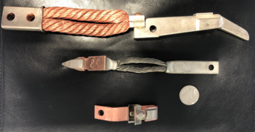
In a typical ATS, there are stationary contact assemblies and moveable contact assemblies. As the name implies, stationary contacts are held in place while moveable contacts have at least one degree of freedom that allows them to make and break the electrical connection by means of an actuating arm. This actuating arm is typically spring-loaded, which minimizes risk of arcing. This concept is explained more fully later in this section.A stationary contact is typically brazed to a copper or bronze backing. The same is true of moveable contacts, but that subassembly is then brazed or mechanically connected to flex connectors that are attached to a ferrule. Within the category of “moveable contacts”, contact assemblies can be further classified into arcing contacts and main (current carrying) contacts. Arcing contacts are responsible for transmitting higher power levels and thus are more prone to arc degradation. As such, these contacts typically have higher levels of refractory in their composition (this concept is further explained in the next section of this briefing titled “Electrical Contact Material Selection”). Figure 3 shows a typical moveable arcing contact assembly, main contact assembly, and a stationary contact assembly, placed next to a quarter for size reference.

Figure 3: From top to bottom; moveable arcing contact assembly, moveable main contact assembly, stationary contact assembly
As is the case with any load switching contact application, the design of the electrical contacts that transmit power is incredibly important. Given the relatively high voltages involved, there is a large risk of arcing (when an electrical discharge “jumps the gap” between the two contacts of the switch). When arcing occurs, transient temperatures can exceed 10,000°F, which can wreak havoc on the materials exposed to this temperature spike. Electrical contacts can experience arc degradation in the form of pitting or even burning when portions of the contact material vaporize and are re-deposited onto the surface of the contact. This can lead to high and unstable contact resistances or even total contact failure.
One way that ATS designers can reduce the risk of arc degradation is through the use of spring-loaded contact mechanisms in conjunction with high contact pressures. By spring-loading the make/break connection, the amount of time the contacts spend near each other is minimized as they are opened and closed. This reduces the window of time in which arcing can occur. When in contact, high contact pressures maximize the asperity of the contacts (asperity is the true surface area of the contacts that are actually touching each other). By pressing the contacts together with a large amount of force, asperity is increased, which ultimately reduces contact resistance and ensures the resistance is relatively stable over time.
ELECTRICAL CONTACT MATERIAL SELECTION
ATS designers can also minimize the risk of arc degradation through proper contact material selection. Some critical material properties of these contacts include:
These properties allow the contact to dissipate heat and electricity quickly, withstand the high contact forces often required in medium- to high-voltage applications, and perform reliably over thousands of switching cycles.
One common electrical contact material found in automatic transfer switches is silver refractory (i.e. silver tungsten, silver tungsten carbide, etc.). A refractory is a material that is resistant to heat, pressure, and chemical influences. The durability of refractories like tungsten and tungsten carbide, combined with the electrical and thermal conductivity of silver, make silver refractories the material of choice for many medium- to high-voltage applications where extensive arcing is expected.
As mentioned earlier in this briefing, moveable arcing contacts typically have larger amounts of refractory in their composition. This serves to increase their temperature capabilities as well as their ability to withstand mechanical wear. This is incredibly important, as it allows the contact to endure harsh arcing conditions and high contact pressures.
CONCLUSION
Given the safety-critical nature of automatic transfer switch design, it comes as no surprise that they are tested rigorously before getting approved for widespread use. UL1008 is one test standard in particular that outlines requirements for transfer switch equipment. Most transfer switch equipment in use today must be UL1008 certified. Ultimately, the end goal is to design an ATS that is capable of thousands of safe, consistent, and reliable switching cycles. The design of electrical contacts in automatic transfer switches is an extensively studied topic that cannot be sufficiently covered in a technical briefing such as this. For more information on electrical contacts, please contact ECL directly with questions or comments.

